3 Tips for Cooling Design in Injection Molding

Improve your productivity in injection molding through properly designing cooling channels.
Many overlook tempering as a critical factor in maintaining productivity and quality in molding shops, even though it accounts for around 40% of energy costs in injection molding. Designing the proper tempering system is one of the main opportunities for improvement in an injection molding plant.
Symmetrical Shrinkage
Heat concentration is the largest source of part warpage. Hot spots in the mold keep enough energy available to induce molecular movement within the polymer during the cooling process, leading to post-molding crystallization and material shrinkage and deformation. To deliver symmetrical shrinkage, the part must experience the same heat transfer rate in every direction. So, the proper channel design and maintenance of the tempering channels are critical to ensuring consistent molding cycles and part quality. The goal is simple: always keep the heat transfer rate as high as possible.
You may also read: Energy Management Systems – Injection Molding 1
1. Run Close to the Cavity
More often than not, tempering channels are designed at the end of the mold design process. Consequently, some regions of the mold have poor tempering.

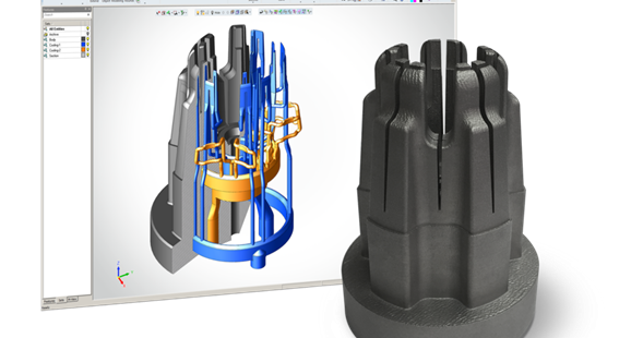
Xact Metal Inserts courtesy of JST Inc.
To ensure mold integrity, the closer the channels can run relative to the part cavity is one diameter (1D) of the cooling channel. So, if for example you are using channels of ½”, then ½” is the closer the channel should be to the mold cavity, to avoid a large stress concentration which may crack the steel.
A technology you may consider when having hard-to-cool inserts or intricate regions within the mold is conformal cooling, enabled by the introduction of additive manufacturing technologies in mold manufacturing.
2. Ensure Enough Area for Heat Transfer
Besides placing tempering channels as close as possible to the mold cavity, ensuring sufficient area for heat removal is crucial. Moreover, the heat transfer area in the mold depends on the tempering channels’ length, diameter, and the number of channels available. A typical diameter in cooling channels lays anywhere from 3/8” to ½”.
Do remember that besides having enough area for heat transfer, you should ensure enough water flow to achieve a turbulent flow regime. Burger and Brown developed a valuable tool called “scientific cooling.” It helps you calculate the correct water flow within mold channels. Additionally, it determines the cooling circuit length to ensure an adequate heat transfer rate.
3. Select the Proper Mold Material

Rovalma, steel supplier based in Spain, provides different steel alloys targeting faster cycle times. The table demonstrates that some grades combine the polishability and wear resistance of typically used alloys such as AISI H13, while significantly improving thermal conductivity. Courtesy of Rovalma.
The heat rate is always proportional to the material conductivity. So, selecting a high conductivity alloy to manufacture your mold or mold inserts will boost your productivity and the rate at which you remove heat from the molded component. Typical mold steels have a heat conductivity of around 12-20 Btu/(hr-ft-°F). However, some ranges of hot work steels may offer thermal conductivities above 45 Btu/(hr-ft-°F). These are remelted tool steels or powder metallurgy tool steels, which often combine high polishability with abrasive resistance. They are known as HTCS, high thermal conductivity steels.
