Printing Process Breaks Composite Tooling Bottleneck
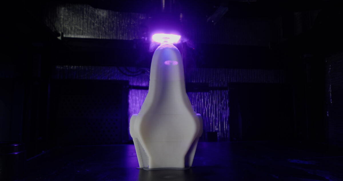
3D printer OEM develops fast, cost-effective process to produce single or double-sided tooling for composite parts
Tool production is often a bottleneck in bringing composite products to market fast and at low cost. Steel molds of modest size and complexity can take months to build conventionally; composite molds, owing to high raw material costs, high scrap rates and a slow and labor-intensive process can take longer.
Additive manufacturing (AM) technologies address these concerns. Mature metal additive technologies are proven methods for fabricating core and cavity components for injection molds producing hundreds of thousands to millions of parts per year. And metal and polymer large-format AM (LFAM) technologies are being evaluated for tooling to form very large composite parts in aerospace, wind energy and defense programs.
From Months to Days
A good example is a patented polymer LFAM system developed by Massivit 3D Printing Technologies Ltd., of Lod, Israel. Massivit is a pioneer in developing complete LFAM systems (including hardware, software, consumables and professional services) that produce large polymer AM parts quickly and cost competitively.
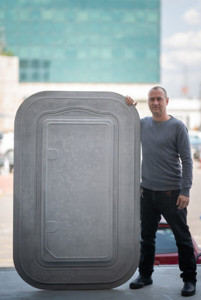
A LFAM system from Massivit 3D Printing Technologies rapidly and cost-effectively produces polymer tooling to mold composite parts. Shown is a boat hatch mold 3D-printed on a Massivit 10000 printer in specially formulated epoxy-based casting material. All photos courtesy of Massivit 3D Printing Technologies Ltd.
Last year the company introduced Massivit 10000 printers designed to automate and fully digitize tool/mold production for composite part manufacturing. The system permits fabricators to manufacture complex, industrial-scale molds in days rather than weeks or months. Finished tools produce composite parts in open- or closed-mold processes.
“Even when machining smaller molds and mold components—which might take only eight to 10 weeks to actually produce—composite toolmakers quote 30-week turnarounds because they have such a backlog of work, and many toolmakers aren’t accepting new customers,” explains Michael Clark, Massivit 3D composites tooling specialist-North America.
“Workflows involve anywhere from 19 steps to produce a mold in composites to 40 steps to produce one in metals. Our process cuts workflow down to four steps. We’re eliminating operations and removing labor by automating and digitizing mold production. Our process can reduce mold production time 80 percent, labor 90 percent and cost 75 percent, which is disruptive in [many] industries.”
The company’s gel dispensing printing and cast in motion (CIM) technologies, which leverage two different thermoset photopolymers, are key to the system’s ability to rapidly and cost effectively print large parts—including molds, mandrels (permanent or wash-away), jigs, fixtures, plugs/masters, geometric cores for composite parts and prototypes. Interestingly, these molds are said to be isotropic, an atypical feature in polymer LFAM systems, which generally are weaker in the Z-axis. Such molds use discontinuous fiber reinforcement to increase mechanicals and reduce slumping, but this introduces anisotropy.
Shell Game
After a CAD model of the geometry is complete and Massivit Smart Slicer software converts the geometry to print paths, the process begins by printing a hollow sacrificial shell structure using a thixotropic acrylic polymer that sloughs off when soaked in water—a feature described as “water breakable.” Called Dimengel WB, the polymer is formulated for use in the Massivit 10000 printer and cures nearly instantaneously as the print head lays down one layer of material over another and is immediately followed by a UV light source.
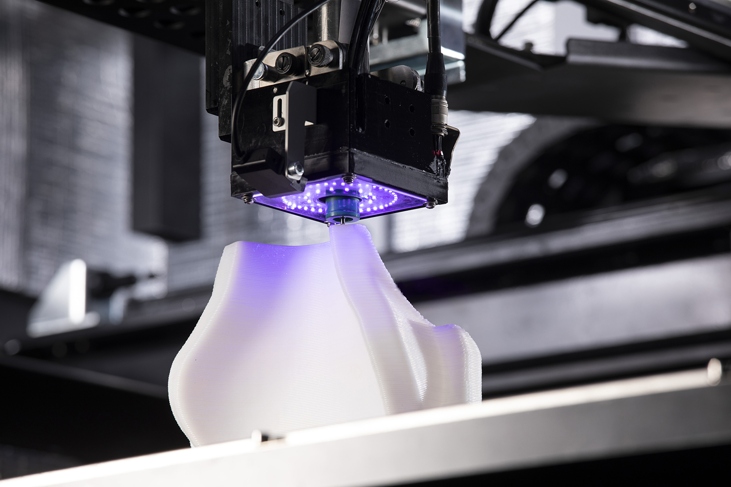
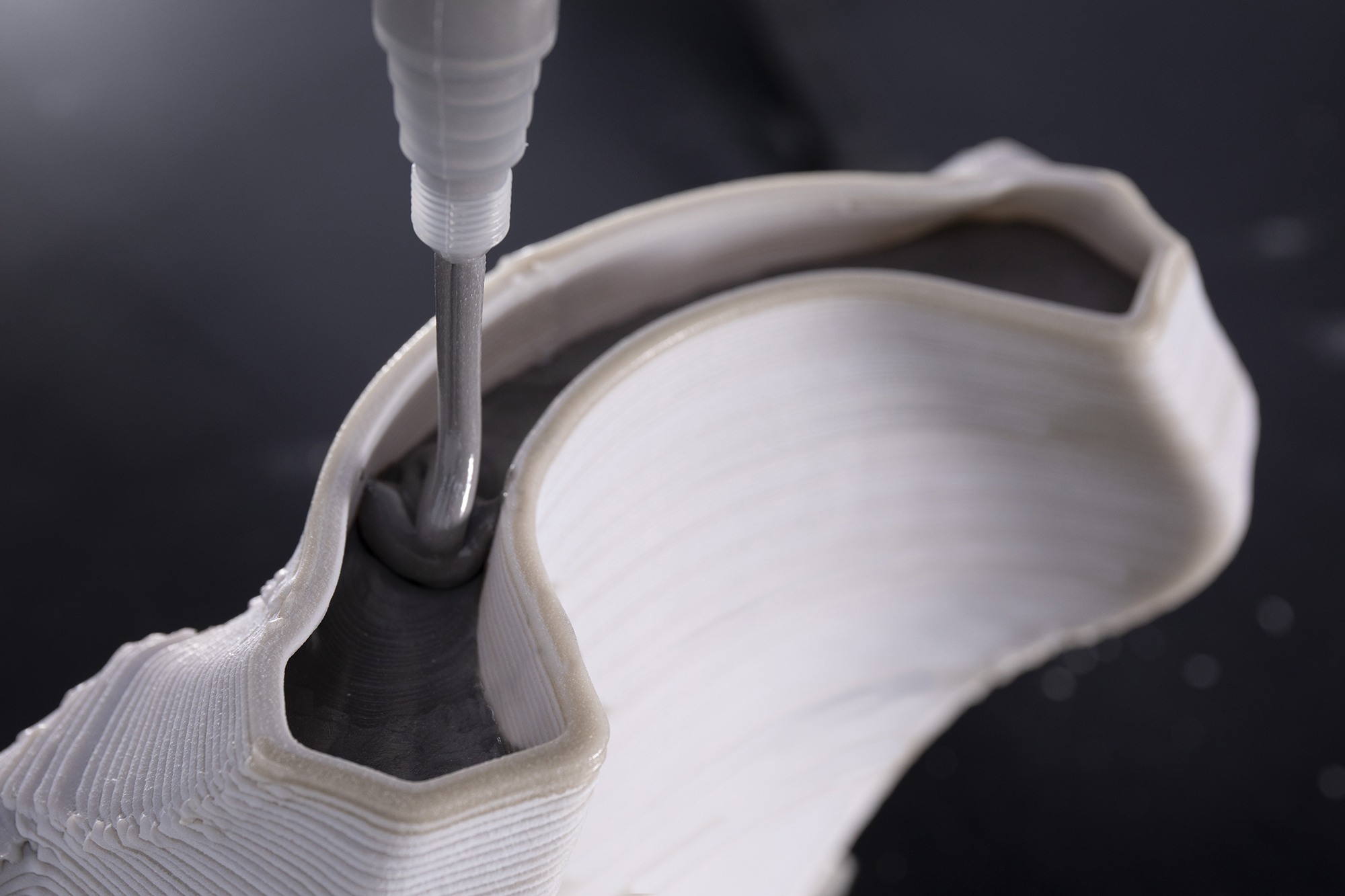
Two photopolymers—one that prints a sacrificial shell (white outer structure at top) and one that forms an isotropic structural epoxy mold (dark grey material dispensed inside shell in lower image)—are key to Massivit’s moldmaking system.
After the print head lays down 8-10 layers of shell material, a second casting head deposits then UV cures a two-part structural epoxy called CIM 500 that will eventually form the body of the finished mold. A mixing unit adjacent to the printer keeps polymer components separate and controls temperature and viscosity. They are brought together in the printer’s mixing head just as the material is cast into the shell structure.
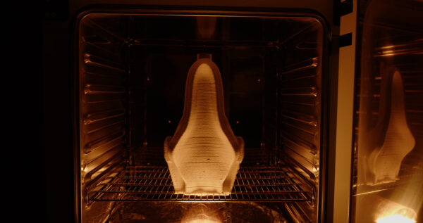
After printing, the workpiece moves to an oven to cure the epoxy and boost its mechanical properties.
Modified epoxy, also specially formulated for Massivit’s process, has good thermal stability (glass transition temperature = 156°C/312°F and heat deflection temperature = 152°C/305°); good mechanicals (tensile strength at break = 50.00 ± 3.1 megapascals/7,250 ± 450 pounds psi); compressive strength (119 megapascals/17,260 pounds psi); true isotropy, thanks to cross-linking through the pour layers; and a linear coefficient of thermal expansion (CLTE) near that of aluminum.
A company goal is to boost thermal stability of the epoxy to 180°C/356°F and lower CLTE to enable autoclave curing of parts.
Because only a small amount of epoxy is dispensed at a time—enough to fill the 8-10 layers of the shell material—the exotherm of the curing epoxy can be controlled, preventing cracks and other issues during cure.
After printing, the workpiece is placed in an oven at 160°C/320°F for 8-10 hours to cure the epoxy and maximize its mechanicals. Then the workpiece is moved to a water bath where the soluble shell sloughs off in 24-30 hours to expose the near-net-shape part inside. Massivit says faster shell removal can be accomplished by exposing the shell to a water/fog system or by mechanical means.
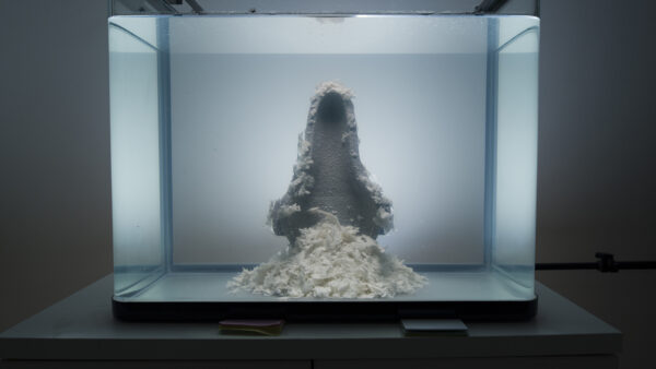
Next, the workpiece spends time in a water bath, causing the sacrificial shell to slough off, leaving a durable epoxy tool.
Next, the epoxy part is sanded, buffed and polished to achieve the required finish on the molding surface/face sheet. For small parts, hand finishing is acceptable; for large parts, CNC machining may be preferable to save time. For those seeking faster ways to finish molds, Massivit has identified a third-party, self-leveling spray coating system whose materials match the CLTE of the epoxy, or gel-coat technology can be used as long as CLTEs match to avoid cracks or delamination. Mold release can be applied prior to forming composite parts.
By first printing a sacrificial shell, then casting the structural epoxy inside, very large and thick parts with complex geometries can be produced rapidly. The system is said to achieve linear print speeds of 300 millimeters/12 inches per second or 3,500 millimeters/138 inches in the Z axis per hour.
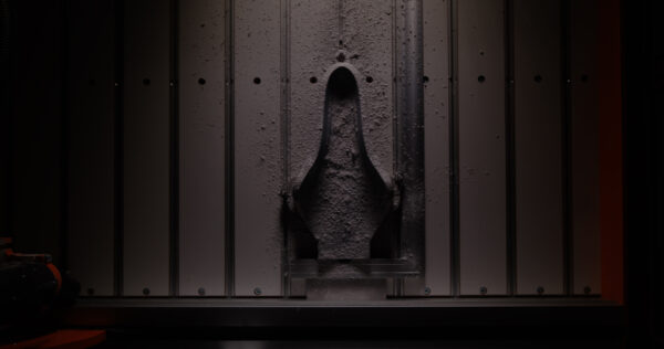
Finally, the mold’s forming surface (face sheet) is machined prior to buffing/polishing and sealing. After application of mold release, the tool is ready for use.
The design freedom of 3D printing and low viscosity of the uncured epoxy facilitate creation of functional features—like integral clamping, support structures and handles, eliminating the need for metal frames—and intricate geometries (print resolution is said to be 1 millimeter/meter of length) without the need for infills or external supports. The process can also produce hollow epoxy parts via a three-layer sandwich of sacrificial shell (mandrel) inside the durable epoxy layer, which is surrounded and supported by another layer of sacrificial shell. In this way, complex 3D tubular structures with soak-away mandrels can be made.
The Massivit 10000 has a print envelope of 1,420 x 1,110 x 1,500 millimeters/42 x 39 x 41 inches. If that volume is insufficient, smaller parts can be printed and bonded together with a methyl methacrylate adhesive whose CLTE is close to that of the epoxy.
Since the process is new, mold durability is not fully defined. However, customers report that molds produced on the system can produce hundreds, if not thousands of parts.
The company’s latest equipment innovation, Massivit 10000-G, combines the best of its moldmaking and part-making printers, since it can also be used for custom part and functional prototype manufacturing and runs the range of Massivit’s Dimengel materials to achieve functional performance like flame retardance and high printing definition.
Parts From Tools
Massivit 10000 technology was vetted by beta customers in North America, Europe and the Middle East and the company is shipping production machines around the world. Composite parts produced on molds from the Massivit process include:
- Carbon composite race car seats
- Motorcycle fairings and ground-effects parts for sports cars
- Bicycle seats
- Aerospace and defense parts.
- 3D ducting with a soak-away mandrel
- Marine consoles and swim platforms that are subsequently glassed over and gel coated and produced faster than conventional glass-fiber parts
- Replacement parts for legacy programs whose original tools are lost
- Full-size car doors for prototyping to replace clay models and tooling board
- Luxury bathware
